Friday, June 10, 2011

Testing Diodes

The last lesson in electrical was on Diodes.

Identify the direction of flow through the diode:

 This is the diagram I did in class, showing the Anode and Cathode, as well as the direction of flow.

Measure the resistance of the diode in both directions using 2k Ohms position on the meters:
Anode to Cathode:   0 (infinity) Ohms
Cathode to Anode:    0 (infinity) Ohms

Check the voltage supplied at the meter probes in the ohms position on the meters, with another meter set it to DC volts.
 Result: 0.61v

Is this enough voltage to theorectically push through the bindery layer of the diode and get an accurate reading?
Yes

Did the Ohm's measurement work?
The Ohms measurement is not effective because we only saw the reading of infinity, which is not the correct reading.

Use the Diode test position to measure the diode in both directions:
Anode to Cathode:    0.539v
Cathode to Anode:    0.L v

Explain what the Diode test position readings mean when you test the diode in both directions and describe whether the diode was good or bad:
The diode test position readings show that the diode is forward bias as eletriity flows one way, but not the other. This is a good diode.

Build a circuit with a diode and a resistor. Use a 1k resistor.

Measure voltage drop across the resistor: 12.75v
Measure voltage drop across the diode: 0.64v
Measure amp flow through the diode:     0.01a
Measure the available voltage at supply: 13.61v
Add the voltage drop together across R & D: 13.39v

Apply the rules of electricity to these readings and describe how these readings demonstrate this.
The rules of electricity for series circuit apply to our readings because our supply voltage was 13.61v, our diode used 0.64v, our resistor had 12.75v and the amp flow equaled 0.01a. When we add together our voltage drop across the diode and resistor it should almost or be completely equal to the supply voltage, according to the electricity law that governs this circuit.

Change the resistor in the circuit to a higher value.
What size did you put in?  2,200 Ohms
Measure the voltage drop across R:  12.82v
Measure the voltage drop across D:  0.61v
Measure amp flow through D:     0.00a


Describe how this change of resistance lead to hanges in your volt and amp readings.
The higher resistance meant that the amperage reading ws barely changed, however it still read 0.00a. There was more overall voltage drop across the resistor but the diode reading stayed the same.

Test an LED.
Anode to Cathode: 1.953v
Cathode to Anode:  0v

Compare the voltage drop of a normal diode and an LED. What does this tell you?
There is more voltage drop in an LED than a normal diode as an LED requires more to power it, therefore it looses more.

Build a circuit with an LED. Use a 1k resistor.

Measure the voltage drop across R: 9.07v
Measure the voltage drop across D: 4.38v
Measure the amp flow through LED: 0.01a
Measure the available voltage supply: 12.45v
Add the voltage drop R & D: 13.45v

Apply the rules of electricity to these readings and compare how these readings are different than the readings for the regular diode.  
 The voltage drop across an LED is more than that of a diode because it uses more to power it, therefore has more to loose. The rules of series circuit apply meaning that the total voltage drop is exactly the amount of supply voltage


Timing Resistor - Capacitor Ciruits with Voltmeters

This lesson we learnt about resistors - capcitor circuits and what capcitor's do.

Calculate how fast the capacitor should charge:

The formula for this is:
Resistance X Capacitance X 5 = Time required to charge.
We also had to convert from  μF to F.

Capacitance                           Capacitance ( F )                   X            Resistance         X     5         Calculated Time
10                                  0.00001                     X          1,000            X    5   =     0.05sec
1                                 0.000001                      X         250,000         X   5    =    1.25sec
100                             0.0001                        X          10,000           X    5    =    5sec
300                             0.0003                      X           4,500             X    5    =    6.75sec


Evaluate the charge time:
Next we had to look at the charge time and determine whether there was enough time to take the readings for each different capacitor before the charge time was up.

Capacitance:      
10μF                    No
1μF                      No
100μF                 No
300F                  Yes


Calculate resistor size:

              Capacitance            Capacitance        
                   (μF)                            (F)
1 -              220                        0.00022        X 5 = 0.001
2 -              330                       0.00033         X 5 = 000165
3 -              100                       0.001            X 5 = 0.0005
4 -              47                         0.000047      X 5 = 0.000235

After we had done all this, then we had to divide 180 (seconds) by the answer above to calculate what size resistor will be needed to have the capacitor charge in about 3 minutes.

1.      180 ÷ 0.0011 = 1636kΩ
2.      180 ÷ 0.00165 = 109kΩ
3.      180 ÷0.0005 = 360kΩ
4.      180 ÷ 0.000235 = 756kΩ

After we had completed these tasks, we then had to build a circuit and then monitor the capacitor charging time verse voltage. Once the circuit was built, we removed the bridge wire and recorded the voltage every 10 seconds for 180 seconds.

10:      3.42v
20:      4.99v
30:      6.83v
40:      8.23v
50:      9.18v
60:      9.93v
70:     10.55v
80:     10.96v
90:     11.28v
100:   11.51v
110:   11.69v
120:   11.83v
130:   11.95v
140:   12.03v
150:   12.09v
160:   12.13v
170:   12.18v
180:   12.21v

After this was completed, we then plotted the data into a graph

Capacitor Charging Report:


The findings in the above graph, show that as the capacitor starts to charge up the speed is fast, however as the volts increase in size, the speed slows down to a steady pace, so as not to overcharge the capacitor.

Identifying,Testing & Combining resistors

Our next lesson was on resistors, which dampen the flow of electricity through the circuit. We learnt how to indentify what the resistors values are, based on their colours and how to calculate that. We also conducted some tests on the resistors.

Colour Identification

Resistors can be indentified with a code, made up of different colours and positions of the bands of colour. The most common types of resistors have only four bands, the first two bands are numbers to write down, the third band colour equals the multiplier and the colour of the last band determines the decimal

Below is the chart we were given to use to work out what each resistors value is.
Identification and combining practice


For this exercise we had to grab six different types of resistors and figure out their value in two ways. First we had to use the colour code to calculate the value and then we had to use the multimeter to measure the resistance value.

Band Colours & No's.                 Measured Val.            Low Tol. Val.             High Tol. Val.
Green, Blue, Brown, Gold             554Ω                         532Ω                         588Ω
 5, 6, 0  ± 5%


Red, Red, Red, Gold                     2170Ω                        2090Ω                       2310Ω
2, 2, 00 ± 5%

Yellow, Violet, Black, Gold           47Ω                             44.65Ω                      49.35Ω 
4, 7 ± 5%


Grey, Red, Yellow, Gold              841000Ω                      779000Ω                   861000Ω
8, 2, 0000 ± 5%


Brown, Black, Red, Gold            984Ω                              950Ω                         1050Ω
1, 00 ± 5%


Brown, Black, Yellow, Gold        98200Ω                           95000Ω                   105000Ω
1,  0000 ± 5%


All of our resistors passed the test, meaning that they were all in good working order.

Pick two resistors and record their individual ohm resistance value measured with a multimeter:
Resistor 1:  2170Ω                   Resistor 2: 984Ω

Put these two resistors together in series and measure their combined value:
1 & 2 in series: 3150Ω

Put the two resistors together in parallel. Measure their combined value:
1 & 2 in parallel: 677Ω

What principles of electricity have we demonstrated with this?
The total resistance will always be less than the lowest resistance in the resistors. It was designed so that the high resistance could go through the parallel circuits and for scientists to calculate Ohms.


Thursday, June 9, 2011

Charging system On - car testing

The next class was testing the charging systems on cars. We had to remember all safety precautions when working around alternators and other components of the charging system. We must remember that if or when we are removing or replacing any alternator wiring or the alternator itself, to disconnect the negative battery terminal first, not to connect the battery in reverse polarity, never short any alternator wires to earth and to never operate an alternator with the output terminal disconnected.

ALTERNATOR OUTPUT ON CAR TESTING

Make of vehicle : Mazda
Model : 323
Year of manufacture : 1981-1985

Preliminary checks before starting to test the charging circuit

Does the charge warning light operate?                               Yes
Are the ignition and all accessories turned off?                   Yes
Visual inspections of connections?                                       Yes
Alternator mounting secure?                                                Yes                                 
Check connection of fuses and fusible links?                      Yes

Inspection of the charging system drive belt condition and tension
The drive belt is in good condition and the tension is good.

Carry out a no load test on the alternator

Battery OCV :              12.56v
Regulator voltage specification :         13.5 - 14.5v
Regulator voltage reading :              13.85v
No Load Amps output specification - Carburettor: 5 - 10Amps
                                                           - Fuel injected: 10 - 18 Amps

No load output:         16 Amps

The regulator voltage reading is within specification. The no load amps output is higher than the specification at 16 amps, when it shoud be around 5 - 10 amps, giving this a failed test result.


Carry out a load test on the alternator 


To do a load test, we must use a clamp induction ammeter and a voltmeter. First set the voltmeter on 20v DC and connect to the battery. Set up the clamp meter to 400 amps DC, then press 'zero' to zero the meter. Place the clamp around the alternator main output wire (B) of the alternator. Start the engine and rev the engine at around 2500, then turn on all accessories possible. Press the hold button on the clamp meter and take the readings from that, and the voltmeter.


Note: Charging voltage under load specification equals OCV + 0.5 = _____ v DC.


Output amps meter reading : 5.7 amps
Charging voltage under load : 12.31 volts
Does the alternator maintain the charging voltage or above? No, it failed to do so.

Carry out a voltage drop test

Obtain the readings for the voltage drop with the engine running at about 1500revs, turn on all accessories.


Check voltage drop between battery positive post and alternator output (B+) 
Specification less than : 0.20v          0.17v1                   PASS

Check voltage drop between battery negative post and alternator body
Specification less than : 0.20v          0.13v2                  PASS

Add all voltage drops together to find the total voltage drop
Maximum allowed 0.40v                  0.30v                    PASS

Summary report of the charging system
The no load test amperage was 16, which is higher than the specification for carburetted engines which is only 5-12 amps, therefore it failed that particular test. When load was applied on the engine it was holding a good voltage drop, however the charging voltage under load was a failed result. Turns out that the wire was loose, so we had abnormal readings for that test, which we then took again after securing the wire. However, nothing changed in the overall report, as the voltage was still less in the charging circuit.


Wednesday, June 8, 2011

Alternator off car testing

In this lesson we were dismantling and testing alternators.

We dismantled the alternators, carrying out a visual inspection on all parts and making sure they looked correct.

Rotor winding to ground test
In this test, we had to use our multimeters on 2K. We placed the black test lead on the centre of the rotor shaft and place the red test lead on the slip rings. In theory, there should be no circuit reading between these parts. If it happened that there was a ciruit, the rotor winding has shorted itself to ground and would need to be replaced. Our meter showed infinity (0), which is a pass.

Rotor winding internal resistance test
We had to set the meter to Ohms at 200. We had to test for internal resistance by touching the two leads together, once we have this reading, we must remember that we have to take away the internal resistance of the meter from the actual resistance reading. We placed each end to the slip rings and obtained the reading, which had to be between 2 to 6Ω

Meter reading - 4.0
Less internal meter resistance - 00.2
Actual - 3.98

This reading gave it a pass result.

Testing the stator winding to ground resistance
For this test we had to set our Ohms meter to 200 and test for internal resistance like before. We had to connect the black lead to the common terminal, which is the point with the most wires. We then connect the red lead to each other terminal one after the other and record the resistance, they should all be the same in theory, ranging from 0.00 - .2 Ω

Meter reading - 0.03         Less internal meter resistance - 0.02      Actual - 0.01
Meter reading - 0.03         Less internal meter resistance - 0.02     Actual - 0.01
Meter reading - 0.03         Less internal meter resistance - 0.02    Actual - 0.01

All our results were within specification and that gave that test a pass result for all three.
The next test we did was testing whether there was any circuit between the stator winding and the ground (body of the alternator) to do this, we set our meters to 2K and placed the red lead onto the common terminal and the black lead to the body of the alternator. The specifications for this are infinity, as there should not be any reading, which is the result we had, meaning that our stator had not shorted and would not need replacement.

Testing the rectifier positive diodes
For this test, we had to place our meter onto the diode testing symbol. We placed the black test lead on the B terminal and touched the positive lead on each of the P terminals, in order to obtain our readings. There should be very low resistance in all of them. We then had to place the positive lead onto the B terminal and touch the black lead onto each of the P terminals, the resistance should be quite high.

Results for positive diode testing with black lead on B

Terminal 1 - .603
Terminal 2 - .605
Terminal 3 - .593
Terminal 4 - .600

The specification for the test above was 0.5VD to 0.7VD, meaning that all of our terminals passed.

Results for positive diode testing with positive lead on B

Terminal 1 - 0
Terminal 2 - 0
Terminal 3 - 0
Terminal 4 - 0

The specification for the test above is infinity, or 0. As the results show, all of our terminals passed.

Testing the rectifier negative diodes
Using the same testing mode as before, place the common lead onto the terminal known as 'E', then touch the positive lead onto each of the P terminals. The resistance should be high on each terminal. Then place the positive lead on the 'E' terminal, and the ground lead to each of the other terminals. Resistance should be low.

Results for the negative diode testing with the ground lead on 'E'

Terminal 1 - 0
Terminal 2 - 0
Terminal 3 - 0
Terminal 4 - 0

Specification for the above test was 0, or infinity, meaning that each of the terminals passed.


Results for the negative diode testing with the positive lead on 'E'

Terminal 1 - .582
Terminal 2 - .630
Terminal 3 - .588
Terminal 4 - .592

The specification for that test was 0.5VD to 0.7VD, meaning that each terminal passed this test as well.

Testing the voltage regulator
To test the voltage regulator in the alternator we use a Transpo voltage regulator tester. To use the tester, we set the voltage controls to 12v and set the current field switch to 0.5amps. Before we can continue though we must find the appropriate information on the voltage regulator in our workbooks, this included wiring diagrams and information charts on each of the different types of regulators.

Wiring diagram for the voltage regulator being tested


Next, after reading the given information on the voltage regulator tester, we must set the 'Field' switch to either 'A' or 'B', which ever the data says for that particular regulator. Then we connect the test leads according to our wiring diagrams. Once this is complete, we can turn on the unit. If the short circuit lamp turns itself on, that means that there is a short circuit happening, in the event of this you must turn off the unit immediately. The field circuit lamp indicates regulator switching frequency, this LED should flash rapidly. The warning light circuit simulator should come on and stay on. The voltmeter should indicate the set voltage according to the information chart for the regulator + or - 1 volt.

Regulator specifications
Part number : IN224
Field setting : A
Voltage: 12v
Set point spec : 14.6
Regulator results
Short circuit light off? Yes                              PASS
Warning light on? Yes                                    PASS
Field light flashing continiously? Yes            FAIL
Set point vantage reading: 12.1                   FAIL
The data gathered shows that the voltage regulator is not regulating the voltage properly through the alternator, shown by the field light not flashing continiously as it should. This conclusion is also backed up by the set point vantage reading only being 12.1v instead of the specification of 14.6v.

Checking the brush protrusion length
To check the brushes of the alternator, we use a vernier calliper to measure the brushes, making sure there is enough length. The brushes are important because they supply electricity to the slip rings and if they are too short the brush springs cant apply enough pressure to maintain the constant contact that is needed, causing excess sparking that damages the slip rings and reduces the output of the alternator. We measured the brushes between the slip ring contact face and the face of the brush holder.
Brush 1 - 15mm    PASS
Brush 2 - 15mm   PASS
The specification for the brush length was 4.0mm minimum, meaning that they passed.

                                                    Overall Alternator Report

The rotor winding to ground test came back as a pass, meaning that there was no ciruit and it had not been shorted. The internal resistance test came back within specifications. The stator winding resistance test came back within specification, with the overall resistance of 0.01Ω. The stator to ground test showed a pass result, meaning that the stator was in perfect working order. The rectifier positive diode tests were a pass as well as the negative diode tests, meaning that no furthur action needs to be taken in regards to them. The voltage regulator test was not as successful, as the field light for the tester which indicates regulator switching frequency, was not flashing indicating that the alternator is not regulating the voltage, meaning that the set point voltage is 12.1v instead of 14.6v. The brushes are in good condition and require no attention. The bearings, although not tested, should be replaced as a precaution. If this were on a customer vehicle I would repair/replace to voltage regulator or quite possibly the whole unit depending on any further tests that could be undertaken.


Battery Testing

Our next subject to cover was batteries and how to test them. For these exercises we had to use a 12v battery, digital multimeter, hydrometer and a high rate discharge tester, otherwise known as a load tester.
 
              Inspecting for battery specifications

For this area of the exercise we had to carry out visual inspections on the battery.

Make of battery: Lucus                            
CCA: 460 Cold cranking amps
Type of battery:  Conventional
Can you get to the electrolyte? Yes
Explain how: Unscrew the cap and remove them.

Are the terminals on the battery clean and tight? Yes
Does the battery show signs of swellings? No
Do any of the areas above require attention? No

                       Checking electrolyte levels

In order to check the electrolyte levels, we must first adorn the required safety gear. Safety glasses and gloves are important because if there is a problem with the battery, or the battery is knocked, battery acid could be poured onto your skin or clothes and cause severe burns, if it gets in your eyes you could be permanently blinded. Safety measures are important with testing batteries for those reasons, but also because the battery acid and fumes around the battery are highly flammable, it is important to keep them in an area away from anywhere or anything that there is a spark. To check the electrolyte levels, we simply look inside the cells to see where the battery fluid is resting. If it is above the cell plates the electrolyte levels are alright and do not need any topping up, if the top of the cell plate is sticking up above the electrolyte then the levels need to be topped up.

Cell 1 Level           Ok
Cell 2 Level           Ok
Cell 3 Level           Ok
Cell 4 Level          Ok
Cell 5 Level          Ok
Cell 6 Level          Ok

                  Battery open circuit voltage test

In order to complete an OCV test on the battery, we must first establish that all possible surface charge has been removed otherwise we will obtain an incorrect reading. To remove surface charge you must turn on the vehicle headlights to drain off the surface charge for around two minutes, turning them off and waiting for a minute and then checking the OCV. OCV is checked by placing the voltmeter on the battery terminals using DC volts as a range.

What voltage did you get? 12.54v
What is the state of charge? 75%-100%
What voltage reading equates to 50% charged? 12.4v
Can you continue with the battery test using this battery? Yes
If the battery happened to be too discharged to load test, what further action would you take? The battery should be left to charge, then be rechecked, but if the battery is still showing below 50%, then the battery would need to be replaced.

                      Testing the battery electrolyte specific gravity

A hydrometer is used to check the specific gravity readings in a battery. To do this, you must place the hydrometer in the battery fluid, then squeeze the top so it pulls the battery fluid up when you release the top. The float inside the hydrometer will tell you the specific gravity. Becareful not to take the hydrometer out of the battery fluid when you are measuring the specific gravity, as battery fluid will drip out of the bottom. This is also an opportunity to inspect the colour of your fluid, which can indicate whether or not your cell plates are corroding, depending on the colour. Grey means that your negative plates are corroding, and brown means that your positive plates are corroding, clear means that there is nothing wrong with your battery plates.

Cell 1 Reading & Colour           1.275 - Grey
Cell 2 Reading & Colour           1.275 - Grey
Cell 3 Reading & Colour           1.275 - Grey
Cell 4 Reading & Colour           1.275 - Grey
Cell 5 Reading & Colour           1.275 - Grey

Cell 6 Reading & Colour           1.275 - Grey
Specific gravity variation of battery:      0
What is the allowable specific gravity variation of your battery: 0-50%
Does the specific gravity of your battery pass? Yes

                        High rate discharge test

Next we must use a load tester to determine the batteries ability to supply cranking voltage, however to perform this test the battery must have at least 50% charge. Make sure that your load tester is swithed off before connecting the leads. Connect the positive lead to the positive terminal on the battery, connect the negative lead to the negative terminal of the battery and apply the specified load by turning the load control knob, the specified load is half of the cold cranking amperage. Wait for the specified time, which is 20 seconds, and take the voltage held and the current readings. When the tester is done, it will beep. Turn off the load tester and disconnect the leads in the reverse order of which you connected them.

What was the voltage held while load was applied? 9v

What was the load current held? 230amps

The reading of 9v is a failed result.The load current held was a pass.

                   Battery Report


What do you recommend needs to be done with this batteryand system?
It would need replacement at some point in the near future due to the corroding negative plates inside the battery cells.

If the terminals were corroded, how would you clean and protect them?
To clean and protect the terminals, you can use a mixture of water and baking soda, however then you must hose off the battery and chassis straight away to avoid rust.

If the battery needed charging, how would you charge it and for how long?
You would charge the battery with a battery charger. You can fast charge the battery for half an hour if you had left your headlights on, this must be charged on 20amps. You can also overnight charge if you just have a flat battery, you must have this on low amps though so as not to overcharge the battery and cause swelling. Overnight charge is usually 12-24 hours.

If the amp draw was too high, how would you track down the problem?
To track down an amp draw, you would use an amp meter and unplug each of the fuses one by one and test them to see which is draining the most amps from the circuit.

The next task we had to was test the battery using a Digital Battery Tester. To test the battery, we must first have the ignition key turned off. Make sure all the battery terminals are clean before connecting the positive clip to the positive terminals and the negative clip to the negative terminal. It will flash up with an error message if your connection is poor. If the battery needs charging, the tester will flash 'CH' or nothing at all, place this battery on charge for a while before continuing. If 'SAE' flashes up on the screen, the tester is working and once you have seen it, you can then set up the tester to the CCA rating of the battery using the controls, make sure that the tester is programmed to 'SAE' first though. Press the test button and wait for the results, if the screen flashes 'PASS' it means that the battery is in good condition and there has been no faults detected. If it flashes 'FAIL', that means something is wrong and you must remove the battery, clean it up and test it again, as sometimes dirty battery terminals can give false results. If it flashes 'SF.CH', that means that the tester has picked up that the battery is carrying some surface charge, which will need to be expelled before testing can continue.

What reading did you get on the display? Fail
What does this tell you about the battery? This tells us that the battery will need replacement.

We then pressed the 'test' button again, which displays the open circuit voltage of the battery and will allow us to work out the state of charge.

What was the OCV of the battery? 12.6v

Pressing the 'test' button again, will give you the cold cranking amperage at that point in time.

CCA: 250

What is the state of charge of the battery? 100%

From the information collected, we would replace the battery due to the failed result on the digital tester and the negative plates being corroded. Alternatively, we could conduct some tests on the charging system to see if there is any fault in there that could be affecting the battery.
      

Tuesday, June 7, 2011

Starter Motor Testing

Starter Motor on car testing

Before we do the actual assesment, we get the opportunity to practice on some of the cars in the workbay.

Make of vehicle: Mazda                       Model: 323
Year of manufacture: 1998

Is the vehicle equipped with an Automatic transmission?          No
Is the vehicle equipped with any device that requires a power source for its memory?       Yes
 
What would you do before you disconnect the battery to ensure no memory loss? 
You would connect a back up 9v battery in the cigarette lighter and then disconnect the battery.

Before we start any testing on the vehicle, we must de - activate the ignition or fuel injection system, so as not to get a shock or have fuel spraying out of the injectors whilst we are conducting testing. We must check the battery for serviceability. After we have selected the correct range on the multi meter and then put the transmission in neutral if it is an automatic, we can then carry out testing.

Check the OCV of the battery:             12.6v
Percentage of charge:                            100%

To check the OCV of the battery we place our positive tester onto the positive terminal of the battery, and place the negative tester onto the negative terminal of the battery, the OCV or 'Open Circuit Voltage' reading will be displayed on the multimeter.

Check the available voltage across the battery terminal whilst cranking the engine:
Cranking voltage specification:             9.5v
Cranking voltage:                                  10.31v

This test is done the same as the OCV test, except that the engine is being cranked while this test is taking place. On this occasion, this battery passed, if it were to fail, it would have to be retested to determine its condition and whether it needs to be replaced.

Next we had to check the starter curcuit for voltage drop.

Check the loss between battery positive post and solenoid starter input stud whilst cranking:
Specification - less that 0.20v              Volts Drop - 0.2v1                       PASS

Check loss across solenoid main input and output terminal studs whilst cranking:
Specification - less than 0.10v              Volts Drop - 0.00v2                    PASS

Check loss between battery negative and starter motor body whist cranking:
Specification - less than 0.20v              Volts Drop - 0.29v3                    FAIL

Maximum voltage drop is:
Maximum allowed - 0.50v                     Total Volts Drop - 0.31v            PASS

Checking the starter motor current draw

Starter current draw specification: 125- 175 amps.

To check the starter motor current draw amps, we had to use a clamp ammeter set to 400 amps DC. We had to zero the meter to gain an acurate reading. Once it was ready for use we had to place the ammeter around the positive battery lead anywhere between the positive terminal and the "B" terminal of the solenoid whilst someone was cranking the engine, pressing hold when the reading came on screen so as not to gain the wrong reading later on.

Starter current draw:              135 amps                       PASS


After this test was completed, we then had to wait for our assesment on the following day, to show what we had learned.


Logic Probe

Next in Electrical we made Logic Probe testers.

                                           Logic Probe Parts List

Brass Rod (150mm long)                               2 Resistors 1KΩ
Red LED light                                                Red alligator clip
Green LED light                                             Black alligator clip
Black wire (2m long)                                     100mm Plastic tube 7mm ld
Red wire (2m long)                                       
Shrink tubing;
Black: 2.4mm diameter, 300mm long

Red: 6.4mm diameter, 175mm long


Black: 12.7mm diameter, 125mm long

Also needed for this exercise is a 12v power supply, digital voltmeter and a soldering iron.

First we viewed the wiring diagram of a Logic Probe that was given to us in our workbooks, once we had studied the diagram we were able to begin wiring it up.

The first step was stripping our long black and our long red wire so that we had enough exposed wires in order to connect up the 1KΩ resistors, which we connected by twisting them around the wire. After we had done this for each wire, we soldered the resistor to the wire to strengthen the connection. Then we grabbed the Green LED and took the positive terminal on it and wrapped it around the other end of the resistor on the red wire, we then did the same with the Red LED on the black wire, then soldered them into place.

Using the small heat shrink, we then insulated both the LED legs and the resistorsfor each wire, making sure they were as overed up as possible, then using the heat gun to shrink the wrap around them, adding even more security and protection.

We then took our brass rod's and ground a point on one end, and made a tin in the middle of the rod aswell, which will make it easier to solder onto. We insulated our brass rod with some more heat shrink for 60mm starting 10mm from the point that we made earlier on the rod. There was a gap left were we had tinned the rod beforehand and then more heat shrink was fitted in order to insulate the blunt end of the rod. We applied the heat gun at this stage to shrink the wrap.

Before we soldered the uninsulated legs of the LED's to the brass rod's tinned area, we had to cut two peices of 15mm shrink wrap and slide it over both the red and black wires together and up onto the rod. After we had got the LED's into position, we grabbed their leg's and twisted them around the rod, making them secure by soldering them to the rod. After that, we used a hot glue gun just underneath the LED bulbs to make sure they were secure.

Next we had to grab the 100mm length of 10mm diameter plastic tubing and cut a slot out of one end, big enough to fit the two LED bulbs plus an extra 5mm. We slid the plastic tube over both the wires and positioned it in the right place, making sure the LED's are both protected and there is an extension of 5mm.

To improve the appearance of our Logic Probe, we had to cut the 20mm length of the 10mm black heat shrink and slide it on from the pointed end of the brass rod, over the top of the plastic tube overhang and close to the Green LED. We then heated it up, making it shrink and holding the plastic tube in it's place. Next we cut a 90mm length of the 10mm black heat shrink and slid it over the wires at the other end of the plastic tubing and shrink it, also holding these wires in position. Cut 20mm lengths of red heat shrink and fit to both ends of the probe, pulling the black heat shrink onto the brass rod and wire tightly.

Twistin the black and red wires around each other neatly, we fitted 15mm lengths of the red heat shrink every 500mm along the wires, leaving the last 300mm of the wires untwisted as we had to still attach alligator clips to the ends of them.

To fit the alligator clips, install the correct way, making sure they are conneted to the appropriate wire. We stripped the insulation and twisted about 10mm of each wire tightly. Inserting the twisted end of the wire through the small hole in the clip, bending them and then securing the insulated section of the wire with the claws provided on the clip. Chopping off the excess parts of the wires once secured, we then soldered the joints together.

Testing:

These Logic Probes are only designed to test 24 volts of less, DC only. Connect the red alligator clip to the battery positive and the black alligator clip to the battery earth. Both red and green LEDs will light up, signifying that there is a connection. Now, touch the brass probe end to the battery positive terminal and the green LED should go out, and the red LED should get brighter. Touch the probe to the earth battery terminal and the red LED should go out, and the green LED should get brighter.

Monday, June 6, 2011

Electrical Circuits: Individual, Series, Parallel & Compound.

Our first lesson in Electrical was testing and creating Individual, Series, Parallel and Compound circuits on a circuit board.

INDIVIDUAL CIRCUITS

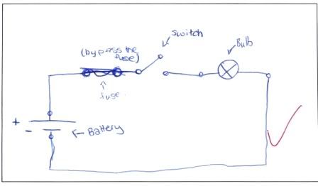
Before we could carry out a test on an Individual Circuit, we had to create the circuit on the circuit board, however, before we could do that, we had to draw a picture of our individual circuit.
We then connected up the Individual circuit on the circuit board, making sure that our light bulb worked and that the circuit was correct. Then we could start to perform our tests. The tests were conducted with a Voltmeter set to DC Volts.
                       Measuring the Available (Supply) Voltage within the circuit

Positive 12v supply (B+)                                          13.40v
Terminal before the switch                                       13.30v
Terminal after the switch                                         13.16v
Terminal before the light bulb                                 13.15v
Terminal after the light bulb                                     0.01v
Negative on the 12v supply (N-)                              0.00v

The table above shows the results we found after testing the individual circuit for the availabe voltage. As you can see, when the battery is available to have load it has 13.40v at the Positive supply. The voltage drops however as it passes through each of the different components in the circuit board that use up voltage. Once it reaches the terminal after the light bulb, the voltage drops drastically to 0.01v,  and once it reaches the negative supply, it is reading 0.00v.

                      Measuring Voltage Drop across the circuit components
From B+ 12v supply to input of the switch                                                0.01v
From input of the switch to output of the switch                                       0.01v
From output of the switch to input of the bulb                                          001v
From the input of the bulb to the output of the bulb                                12.77v
From the output of the bulb to the N- of the 12v supply                          0.01v

The table above shows the results we got after testing the voltage drop in the individual circuit. As you can see, the largest voltage drop came when the volts reached the light bulb, this is because the buld used up almost all of the available voltage, leaving very little left over, however this is not a problem, as the other circuitry does not require a substancial amount of voltage to power the components.

                       Measuring the amps (current) flowing through the circuit


 To measure amp's flowing through the individual circuit, we must hook up an amp meter, in series, into the circuit, once this is done, it will give us our reading. We measured it at the wire before the light bulb which gave us the reading of 0.35amps.

                       Calculating the resistance of the light bulb

To calculate the resistance of the light bulb we must use Ohms Law. Ohms Law to calculate resistance is shown as Volts ÷ Amps = Resistance, or V ÷ I = R.
Using this method, we calculate that:                        13.15 ÷ 0.35 = 37.57Ω
This tells us that the resistance in our light bulb is 37.57Ω

                       Calculating the Watts used at the light bulb

To calculate the Watts used at the light bulb, we must use the Power Law. The Power Law to calculate Watts is shown as Volts x Amps = Watts, or V x I = W.
Using this method, we calculate that:                       13.15 x 0.35 = 4.60W
This tells us that the Watts used at the light bulb are 4.60w.

After we had done these calculations, we then had to create another circuit with a larger bulb.

                      Measuring the amps (current) flowing through the circuit


Current flow through the curcuit                                0.76amps

As you can see from the readings of both the larger bulb amperage and the smaller bulb amperage, the circuit with the smallest bulb has the lowest amperage whilst the circuit with the largest bulb has the most amperage due to the fact that it is larger, therefore it has more load.


                      Calculating the resistance of the light bulb


12.51v ÷ 0.76a = 16.46Ω

The calculations show that the resistance is alot lower in the bigger bulb than it is in the smaller bulb, this is because the bigger bulb has a higher current flow than the smaller bulb.


                      Calculating the Watts used at the light bulb


12.51v x 0.76a = 9.50W

The Watts reading for the larger bulb is higher because the light needs to be brighter, whereas the smaller bulb has a lower wattage due to the fact that it does not need to be as bright.


SERIES CIRCUIT

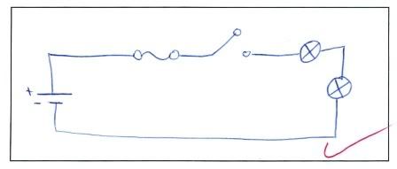
Next, we had to design a Series circuit, which is basically two bulbs put together, in a series. Although there is two bulbs, there is still only one path for the electricity to flow through, it must pass through the first bulb and then the second bulb. Again, we had to draw the circuit first, as shown below.


Once we had drawn the wiring diagram, we then moved on to wiring it up on the circuit boards and checking that it worked.


                       Measuring Voltage Drop across the components

Wire before the switch                                     0.01v
Switch                                                                0.01v
Wire before light bulb 1                                    0.01v
Light bulb 1                                                       10.78v
Wire between light bulb 1 & 2                         0.01v
Light bulb 2                                                       1.61v
Wire after light bulb 2                                      0.01v

Measure the voltage available at the battery            12.53v

From this data, we can see that the voltage was a constant 0.01v through-out the circuit until it reached the first light bulb, which then had a voltage drop of 10.78v. The next reading went back down to 0.01v but then when it reached the second bulb it only had 1.61v as the first bulb had used up all the voltage.


                      Measuring Amps in the circuit

Wire before the switch                            0.32a
Wire before light bulb 1                           0.32a          
Wire between light bulb 1 & 2                 0.32a
Wire after light bulb 2                              0.32a

As you can see, the amperage in series circuits is different to that of the individual circuits. The amperage in the double bulb circuit has dropped beause of the higher amount of resistance from both bulbs compred to the single bulb circuit.

                      Calculate the total resistance of the circuit

12.53v ÷ 0.32a = 39.16Ώ


                      Calculate the Watts used by each light bulb

Bulb 1;
10.78v x 0.32a = 3.44W


Bulb 2;
1.61v x 0.32a = 0.51W


This data tells us that the first bulb has a higher wattage therefore it glows brighter, the second bulb has a lower wattage and does not have enough watts to power the bulb, in addition the resistance is higher in the smaller bulb, which is the first.


After these tests were completed, we proceeded to create a circuit with three bulbs instead of two in series.

                      Measure voltage drop across the different components

Wire before the switch                               0.01v
Switch                                                          0.06v
Wire before light bulb 1                             0.01v
Light bulb 1                                                9.69v
Wire between light bulb 1 & 2                  0.01v
Light bulb 2                                                1.32v
Wire between light bulb 2 & 3                  0.0v
Light bulb 3                                                1.3v
Wire after light bulb 3                               0.01v


Measure the voltage available at the supply               12.46v

The data shows that the first bulb has less voltage than the two bulb circuit.The second bulb and third bulb were not that much different than the two bulb circuit readings however they had considerably less voltage than the first bulb.

                      Measure amps in the circuit

Wire before the switch                                   0.30a
Wire before light bulb 1                                 0.30a
Wire between light bulb 1 & 2                       0.30a
Wire between light bulb 2 & 3                       0.30a
Wire after light bulb 3                                    0.30a

Compared to the two bulb circuit, the amps have dropped 0.02 amps. The amps in this circuit are continiously stable.

                     Calculate the total resistance of the circuit 

12.46v ÷ 0.30 = 41.53Ω

                     Calculate the Watts used at each light bulb 

Light bulb 1;
9.69v x 0.30a = 2.9W


Light bulb 2;
1.32v x 0.30a = 0.39W


Light bulb 3;
1.3v x 0.30a = 0.39W


These readings show us that these bulbs arent reading high wattage, however the first bulb is still glowing. The circuit takes up quite a bit of the load aswell as the first bulb. On the two bulb circuit it has higher wattage because there is less to use up the load on the circuit.


                   Use the available voltage method to measure voltage in the circuit

For this test, we started at the positive side of the battery and measured the different parts of the circuit.

Battery positive                                              13.38v
Input to the switch                                          13.36v
Output of the switch                                       13.36v
Supply to light bulb 1                                     13.36v
Output of light bulb 1                                     3.19v
Input to light bulb 2                                        3.23v
Output of light bulb 2                                     1.8v
Input to light bulb 3                                        1.86v
Output of light bulb 3                                      0.21v
At the negative of the supply                         0.00v

What do the different readings tell you when using voltage drop compared to available voltage?
Available voltage is measuring how much voltage is available in the circuit at any one component whilst voltage drop is measuring how much voltage drops between each component in the circuit.
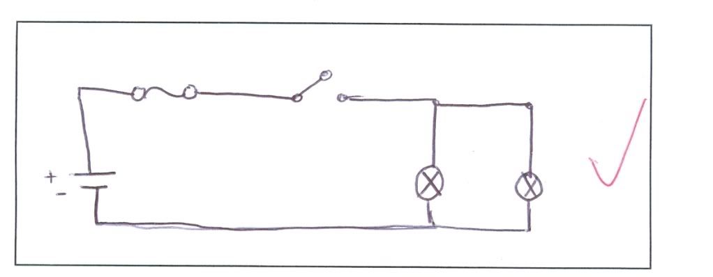

Parallel Circuits

In a parallel circuit each of the consumers have their own B+ supply and N-.
We had to draw a wiring diagram and then create the circuit on our circuit boards, then conduct testing.


                           Measure available voltage at each light bulb in parallel

Light bulb 1                     12.42v
Light bulb 2                     12.43v

                           Measure voltage drop across each light bulb in parallel

Light bulb 1                     12.38v
Light bulb 2                     12.29v

This data shows that the supply voltage goes from the positive and negative and travels through the bulbs with the same main voltage, making the lights glow, as they now have their own circuit.

                           Measure the current flow (amps) through the parallel circuit

Current flow through light bulb 1 circuit                0.74a
Current flow through light bulb 2 circuit                0.70a
Total current flow through both circuits                 1.44a

The rule applied to parallel circuits is that the current is different, this is different to series circuits as the current stays the same for them. This data backs that up, showing that the current is different compared to the series circuit results.

                          Calculate the total resistance of each bulb in the circuit

Light bulb 1;
12.38v ÷ 0.74a = 16.73Ω

Light bulb 2;
12.29v ÷ 0.70a = 17.56Ω

                          Calculate the total resistance of the circuit using the formula given

1/RT = 1 ÷ 16.73 + 1 ÷ 17.56
         = 1 + 1.05 ÷ 17.56
         = 2.05 ÷ 17.56

RT/1 = 17.56 ÷ 2.05
         = 8.57Ω 

                          Calculate total watts used in the parallel circuit whilst both lights are on

Wt = W1 + W2
      = 9.16 + 8.60
      = 17.76W

                          Calculate watts for each individual bulb

Bulb 1;
W = V x I
    = 12.38v x 0.74a
    = 9.14W


Bulb 2;
W = V x I
    = 12.29v x0.70a
    = 8.60W

As you can see, these circuits use more wattage than a series circuit would.

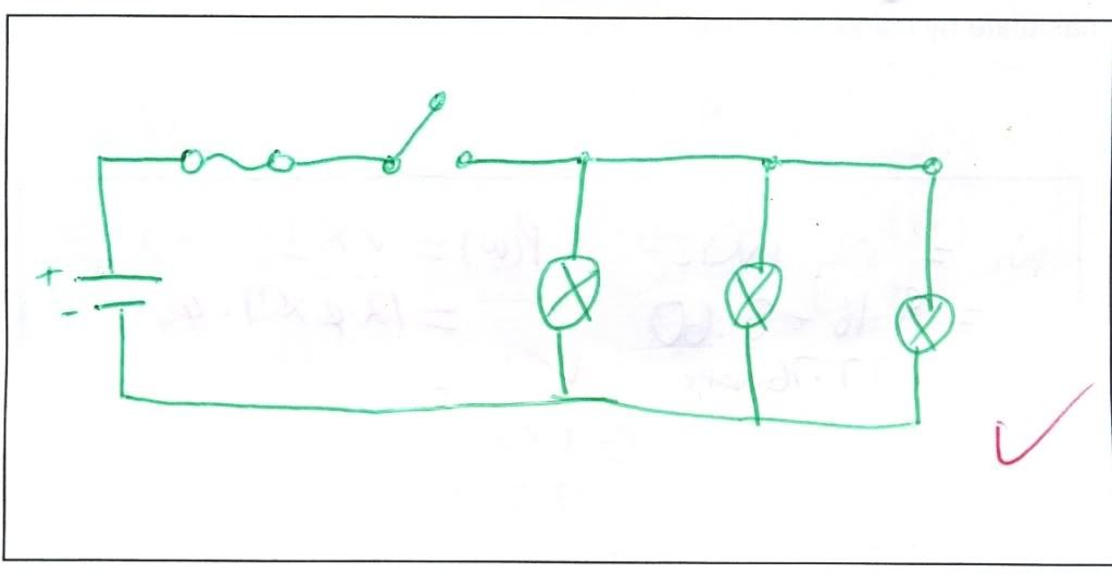
Next we had to draw a wiring diagram for a parallel circuit with three bulbs.


                      Measure the current (amps) flow through each of the 3 light bulbs circuits

Current flow through light bulb 1 circuit                    0.32a
Current flow through light bulb 2 circuit                    0.74a
Current flow through light bulb 3 circuit                    0.70a
Total current fow through all the circuits                   1.76a

As you can see from the results, the first bulb had lower amperage as it was a smaller bulb. The other two bulbs were bigger, therefore they showed a smaller drop in amperage between the two of them. This also illustrates the rule of parallel, which is that the current is always different in the circuit.

                     Measure available voltage in the circuit now that there are three bulbs

Light bulb 1                   12.68v
Light bulb 2                   12.75v
Light bulb 3                   12.73v

                    Measure voltage drop across each of the bulbs

Light bulb 1                   12.54v
Light bulb 2                   12.52v
Light bulb 3                   12.45v

Looking at the data on the available voltage in the circuit now that the third bulb has been added, there was no substancial change compared to that of the two bulb circuit. The voltage drop in the circuit now that the third bulb had been added was slightly lower than that of the two bulb circuit.

                     Calculate the resistance of each bulb

Bulb 1;
R = V ÷ I 
   = 12.68v ÷ 0.32a
   = 39.62Ω

Bulb 2;
R = V ÷ I
    = 12.75v ÷ 0.74a
    = 17.23Ω

Bulb 3;
R = V ÷ I
   = 12.73 ÷ 0.76
   = 18.19Ω

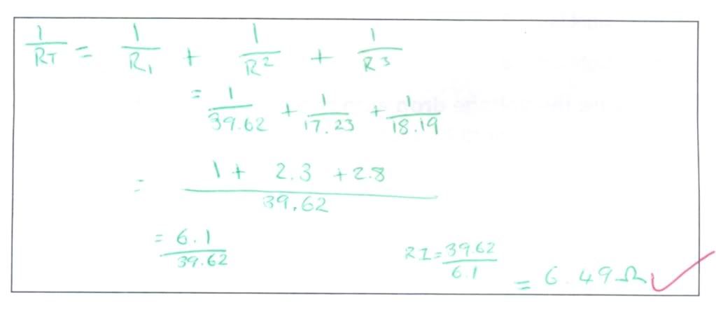
                   Calculate the total resistance of the circuit using the given formula

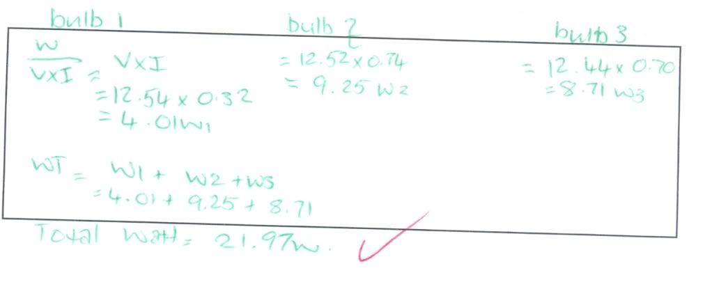
                   Calculate total watts used in the parallel circuit with three lights on
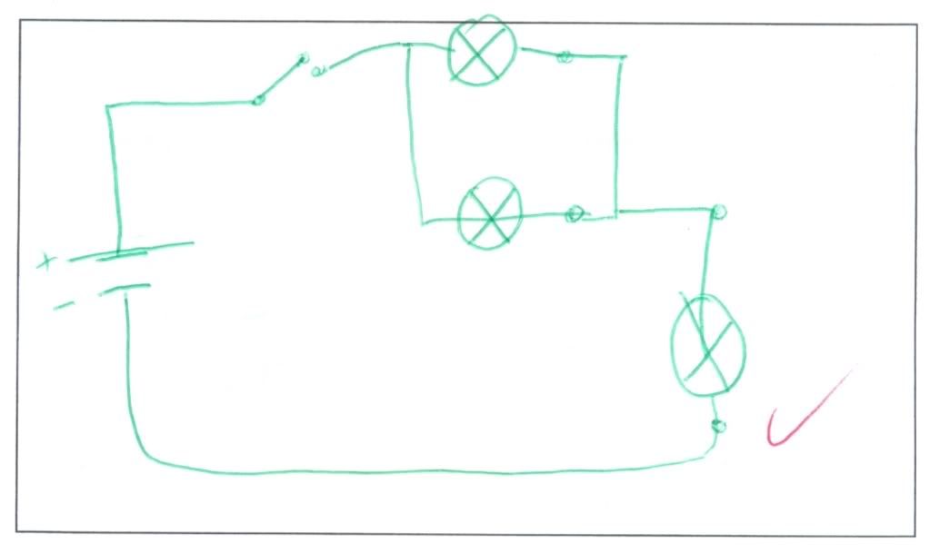


Compound Circuits

Compound circuits are made up of part series and part parallel combinations. Below is a wiring diagram of what a compound circuit may look like.


                            Measure available voltage at different parts of the compound circuit

Switch                                                              12.61v
Before parallel light bulb 1                             12.59v
Before parallel light bulb 2                             12.59v
After parallel light bulb 1                                8.79v
After parallel light bulb 2                                8.78v
Before series light bub                                    8.77v
After series light bulb                                      0.08v


                             Measure the voltage drop at different parts of the compound circuit

Across parallel light bulb 1                               3.80 Voltage drop
Across parallel light bulb 2                               3.79 Voltage drop
Across series light bulb                                    8.64 Voltage drop

                          
                             Measure the current flowing through the circuit at given points

The switch                                                       0.59 amps
Parallel light bulb 1                                         0.16 amps
Parallel light bulb 2                                         0.41 amps
Series light bulb                                              0.59 amps

                             Calulate watts used at each parallel light bulb

Light bulb 1;
W = V X I
3.80v x 0.16a
= 0.608W

Light bulb 2;
3.79v x 0.41a
= 1.554W

                            Calculate watts used at the series light bulb

Light bulb 3;
8.64v x 0.59a
= 5.098W

From the calculations, we can see that the bulb in series circuit uses up the most watts, only leaving a small amount for the two bulbs on the parallel circuit. The series bulb also effects the brightness of the bulbs in the parallel circuit because the series bulb is using up the main amount of current flow in the circuit which the parallel bulbs would usually use to power themselves, meaning that the bulbs will be dimmer as there is not enough current flow to support them. As for the amperage, the bulb in the series circuit gets the most current through it, meaning the amperage is higher while the parallel circuit gets the same amount of amperage, however it is shared between the two bulbs. The bulbs on the parallel circuit get an equal amount of voltage but takes away voltage through the voltage drop which then becomes used by the bulb in the series circuit.