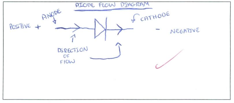
Identify the direction of flow through the diode:
Measure the resistance of the diode in both directions using 2k Ohms position on the meters:
Anode to Cathode: 0 (infinity) Ohms
Cathode to Anode: 0 (infinity) Ohms
Check the voltage supplied at the meter probes in the ohms position on the meters, with another meter set it to DC volts.
Result: 0.61v
Is this enough voltage to theorectically push through the bindery layer of the diode and get an accurate reading?
Yes
Did the Ohm's measurement work?
The Ohms measurement is not effective because we only saw the reading of infinity, which is not the correct reading.
Use the Diode test position to measure the diode in both directions:
Anode to Cathode: 0.539v
Cathode to Anode: 0.L v
Explain what the Diode test position readings mean when you test the diode in both directions and describe whether the diode was good or bad:
The diode test position readings show that the diode is forward bias as eletriity flows one way, but not the other. This is a good diode.
Build a circuit with a diode and a resistor. Use a 1k resistor.
Measure voltage drop across the resistor: 12.75v
Measure voltage drop across the diode: 0.64v
Measure amp flow through the diode: 0.01a
Measure the available voltage at supply: 13.61v
Add the voltage drop together across R & D: 13.39v
Apply the rules of electricity to these readings and describe how these readings demonstrate this.
The rules of electricity for series circuit apply to our readings because our supply voltage was 13.61v, our diode used 0.64v, our resistor had 12.75v and the amp flow equaled 0.01a. When we add together our voltage drop across the diode and resistor it should almost or be completely equal to the supply voltage, according to the electricity law that governs this circuit.
Change the resistor in the circuit to a higher value.
What size did you put in? 2,200 Ohms
Measure the voltage drop across R: 12.82v
Measure the voltage drop across D: 0.61v
Measure amp flow through D: 0.00a
Describe how this change of resistance lead to hanges in your volt and amp readings.
The higher resistance meant that the amperage reading ws barely changed, however it still read 0.00a. There was more overall voltage drop across the resistor but the diode reading stayed the same.
Test an LED.
Anode to Cathode: 1.953v
Cathode to Anode: 0v
Compare the voltage drop of a normal diode and an LED. What does this tell you?
There is more voltage drop in an LED than a normal diode as an LED requires more to power it, therefore it looses more.
Build a circuit with an LED. Use a 1k resistor.
Measure the voltage drop across R: 9.07v
Measure the voltage drop across D: 4.38v
Measure the amp flow through LED: 0.01a
Measure the available voltage supply: 12.45v
Add the voltage drop R & D: 13.45v
Apply the rules of electricity to these readings and compare how these readings are different than the readings for the regular diode.
The voltage drop across an LED is more than that of a diode because it uses more to power it, therefore has more to loose. The rules of series circuit apply meaning that the total voltage drop is exactly the amount of supply voltage
No comments:
Post a Comment